How PCI-Express and PCI work: An Introduction

Peripheral Component Interconnect (PCI) was developed by Intel as a processor-independent bus. PCI is completely in the public domain and became established as a standard for high-speed connections of peripheral devices to the motherboard. Because of its versatility, it has increasingly been used in server systems in the 1990s.
PCI Express (PCIe) is a high-speed serial computer expansion bus standard developed as a PCI successor based on Point-to-Point Interconnect. It connects peripheral devices to a computer’s motherboard, such as graphics cards, sound cards, network cards, and storage devices.
PCI-Express vs. PCI
Since PCI is a bus-based standard, it has the same speed limitations as other bus-based systems. As PCI-Express is based on Point-to-Point Interconnect, it enables significantly higher data rates that come with data-intensive applications such as real-time high-resolution video streaming. Contrary to PCI, which is a parallel interface, PCIe is a serial data interface.
The PCI standard enables data rates of up to 133 MB/s. PCIe, in its latest generation (as of this writing, generation 4), enables a speed of 2 GB/s per lane. A PCI-Express lane has two pairs of wires that transmit data in both directions. A PCI-Express interface with 16 lanes is described as a 16x interface. The standard commonly uses 16 lanes resulting in a throughput of 32GB/s. For some devices like GPUs, 16 lanes are the minimum requirement to enable the required throughput.
How PCI-Express Works
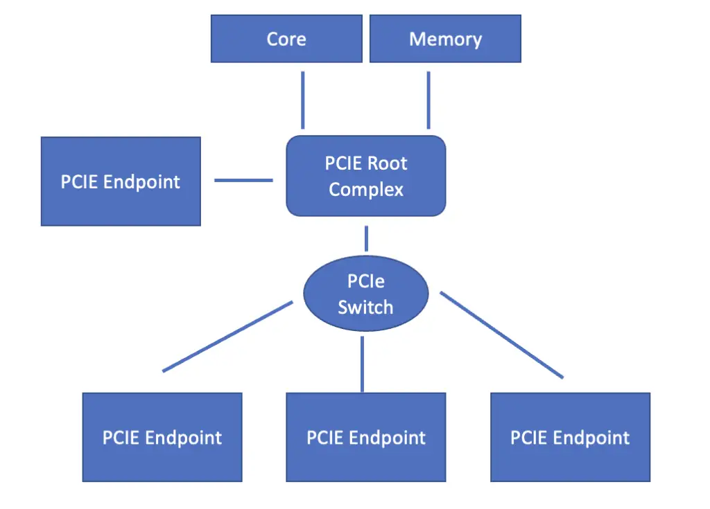
At the core of the PCI Express configuration is the root complex. It constitutes the bridge between incoming PCI Express connections on the one hand and the processor and memory on the other hand. The job of the root complex is to translate between the incoming PCI-Express format and the data transmission format required by the processor and memory. It also modulates differences in data rates.
PCI-Express endpoint from I/O devices can either connect directly to the root complex, or they can connect through a switch that manages multiple incoming PCI-Express streams.
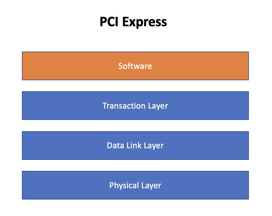
Like QPI, PCI-Express works based on three layers of the OSI model. These are the physical layer, the data link layer, and the transaction/routing layer. On top of these three layers, PCIe has a software layer that is responsible for generating the requests necessary for transmitting data packets.
Physical Layer
At the heart of the PCIe physical layer are pairs of wires that constitute lanes for bidirectional data transfer. PCI ports support connections of up to 32 lanes, although 16 is more common.
When evaluating PCI-Express performance, you may see a field called line code that contains a value such as 128b/130b. The line code designates the package size as well as the ratio of information bits to total bits transmitted. Since PCI-Express 3.0, each lane is designed to transmit data in 16-byte packages corresponding to 128 bits. A header of two bits is added for data stream synchronization resulting in a total package size of 130 bits. The header tells the receiver when there is a transition to a new information package so it can synchronize with the transmitter.
Data is transmitted using a technique called differential signaling, which applies two complementary signals to transmit bits. The two signals are transmitted using two conductors. The information is extracted by the receiver by measuring the difference between the two signals.
When using differential signaling, a string of the same bit value may be transmitted. This could result in a loss of synchronization because the receiver may not be able to distinguish between the header denoting the beginning of a new message, and a random part of the message.
To overcome this problem, PCI-Express uses bit scrambling, a technique that makes the data appear more random. Scrambling results in more transitions between bit values and, thus in more variations in the signal. However, the process by which bits are scrambled is pseudorandom and not truly random. Otherwise, it wouldn’t be possible to reconstruct the original data. The reconstruction of the original data is the job of the descrambler, which sits at the end of the transmission process.
Transaction Layer
The transaction layer is responsible for packaging the data into chunks for transmission. Transmission is usually done via the split transaction technique. In the split transaction technique, the device from which the signal originates sends out a request packet. The receiver processes the data and sends a completion packet back to the originator upon completion of the request. Packets usually contain unique routing information that enables senders to route packets to the correct receiver. A packet contains a header. It optionally may also contain a data payload that is used for error correction.
The transaction is called split because the transmission of the request packet and the return of the completion packet are two separate transactions that can be processed asynchronously. Between the two transactions, other traffic can even use the connection. Transactions are either read or write transactions. If transactions are required to be atomic, the root complex can lock the PCI-Express link so that requests follow consecutively with nothing happening between them. These are known as locked transactions.
Some transactions do not expect a response, meaning the sender does not send a request waiting for a completion packet, but only posts a data packet and then moves on to the next transaction. Accordingly, these transactions are called posted transactions.
Each transaction consists of one or more packets. Packets generally map to 32-bit or 64-bit address spaces known as words. A packet is assembled in the transaction layer of the originating device. The transaction layer receives the information required for routing from software running on the upper layers. Ultimately, the packet is routed to the transaction layer of the receiving device.
PCI Express Transaction Types
PCI Express and PCIE-compatible devices support four address spaces corresponding to four transaction types.
- Configuration Space/Transaction: The configuration space contains information about a PCI-Express compatible peripheral device’s capabilities. The system host can configure the peripheral device to use the registers in the configuration space.
- Memory Space/Transaction: The memory spaces allow the system host to read data from and write data to the system’s main memory.
- I/O Space/Transaction: The I/O address space is for legacy PCI devices.
- Message Space/Transaction: This address space signals interrupts, and transmits error messages. A message transaction is usually posted. It is an addition in PCI Express and did not exist in PCI configurations.
We’ve covered a lot of information. Let’s have a look at a few requests to see how they work in practice.
Non-Posted Read Transaction
A non-posted read request is issued by a sender to a receiver whom the sender intends to read data from. Non-posted read requests encompass memory read requests, configuration read requests, and I/O read requests. The sender can be a root complex or an endpoint device.
Using the information received from the upper layers, the transaction layer creates a header and appends it to the data it wants to transmit. Optionally, it also adds a payload for error correction. Based on the information in the header, the packet is routed to the receiver. The receiver can also be a root complex, an endpoint, a switch, or a PCIe bridge.
Upon receipt, the receiver decodes the contents of the read request and identifies the addresses of the information requested by the sender. It then retrieves the requested data and assembles them into packets that are returned to the sender as a so-called completion packet.
Locked Transaction
Locked requests are used when the requests should be atomic. When a device wants to perform a locked transaction, it sets a bit in the header of the transaction request indicating that the transaction should be locked. This way, other devices on the bus know they should not send any transactions that could potentially interrupt the locked transaction.
Non-Posted Write Transaction
In a non-posted write transaction, the sender transmits a non-posted write request to the target (the device that will receive the data) and waits for a response. Upon receipt, the receiver decodes the contents of the packets and sends a completion message consisting of a single package back to the sender. It thus acknowledges receipt of the data and informs the sender whether the write request has succeeded. If the write operation did not succeed, the completion package would contain an error. The completion packet contains the routing information in the header to find its way back to the sender. Non-posted write requests encompass configuration write requests, and I/O write requests.
Posted Write Transactions
Memory write transactions are posted, which implies that they don’t return completion packets to the sender. Not waiting for a completion packet significantly improves system performance by allowing the initiator to continue with other transactions while the target stores the data in a buffer and processes it later. This can reduce the number of cycles that the initiator must wait for a response, which positively affects system performance. An obvious drawback of a posted transaction is that the sender is not informed whether the write operation has succeeded or not. Usually, a certain amount of errors can be mitigated by error correction software.
Just as with non-posted transactions, the request header contains the routing information.
Data Link Layer
As the name implies, the data link layer creates and maintains a reliable link between two devices. More specifically, the data link layer is responsible for:
- Initializing the link between two devices when they are first connected
- Managing the flow of data across the link by performing tasks such as packetization, error checking, and flow control
- Resending packets that are not acknowledged as received by the other device
- Detecting and reporting link-level errors
In essence, the data link layer is responsible for transmitting the packets generated by the transaction layer. The data link layer at the sender adds two fields to the transaction layer packet that are used by each intermediate node to determine how to route the packet to its final destination and to handle error detection.
Once the packet arrives at the receiving device, it checks for errors using one of the fields appended by the sender. If no errors are detected, the data link layer passes the packet to the transaction layer. If errors are detected, the receiver returns a packet at the data link layer, informing the sender that the packet received was faulty. In that case, the sender will retransmit the packet.
