From the Computer Bus to Point-to-Point Interconnect: An Overview of Bus Interconnection Structures

A bus in computer architecture is a medium for transmitting information between devices. In a typical computer, you have a central processing unit, system memory, and some I/O devices that need to communicate with each other. Busses connect all of these components together as a shared transmission medium. This means a signal sent by any device can be received by any other device connected to the bus. It also means that only one device can send at a time. If there were more than one signal traveling on the bus during a clock cycle, the signals would overlap.
In modern computer systems, buses have largely been replaced by point-to-point interconnection pathways that allow devices to communicate directly with each other rather than through a shared bus. It still is worth understanding how they work because it will improve your understanding of how modern communication architectures evolved. Furthermore, buses are still used in many embedded systems.
How Does a Bus Work in Computer Architecture?
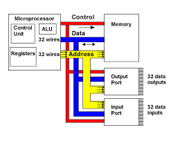
In traditional computer architectures, we have a single processor with a set of pins that are used to send electrical signals via a connection to the main memory. Using these signals, the processor can communicate the address as well as the data to the main memory. The operations of memory and the processor are synchronized via the bus.
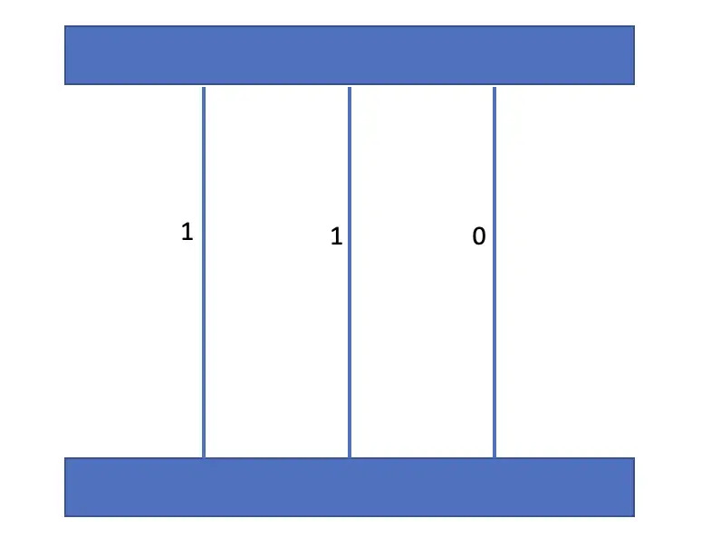
A bus consists of so-called lines that allow electronic signals to travel between components. Traditionally, a line could send a single bit per bus cycle. To increase the bandwidth and send more than a single 0 or 1 per cycle, multiple lines can be used to transmit bits in parallel. For example, 16 lines can be used to send 16 bits at once. Accordingly, the bus system is referred to as a 16-bit bus.
Bus Multiplexing
The fact that only one bit can be sent per line becomes impractical as the size of signals grows. Bus multiplexing allows for sending more signals via fewer lines. For example, a 32-bit address can be sent via a 16-bit bus by splitting the address into two equal-sized parts and sending them through two cycles.
The System Bus
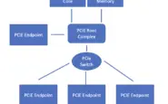
Busses typically consist of 50-100 lines that connect various components in a computer. System buses generally enable communication between the CPU, the main memory, and I/O. I/O devices can be anything from graphics processing units to printers and keyboards. They are usually connected to the system bus via an external bus using a so-called bridge. The system buses generally fall into one of three categories.
- The lines of the data bus are used to move data between system components.
- The address bus communicates the address of the data to be retrieved between the CPU and main memory or an I/O storage device. The width of a bus that does not use multiplexing determines how many memory locations are addressable. For example, a 32-bit address bus yields a total of 2^32 = 4.29 billion possible address locations.
- The control bus is used to control how the components access the data bus and the address bus. Since all components have access to the bus, control is important to prevent signals from overlapping.
To send data, a component must acquire control over the control bus and then send data via the data bus. To receive data, a component must obtain control via the control bus and then specify the address of the data it wants via the address bus.
Memory Bus vs. Address Bus vs. Data Bus
People often end up confused with the terms used to describe the different types of buses.
The term memory bus is often used interchangeably with the data bus. But actually, the memory bus describes the whole internal bus system that is required for the processor to communicate with memory. It is, thus, one level higher on the abstraction hierarchy than the address bus and the data bus.
In order to obtain data from memory, you need to know where that data is stored. The address bus is used by the processor to send the memory address to the main memory. Since the address only flows in one direction, the address bus is unidirectional. The data bus then enables the processor to retrieve data from the specified location or send data to the specified memory location. It is, thus, bidirectional.
The memory bus consists of the data bus and the address bus.
Control Bus
The job of the control bus is to coordinate the orderly transfer of data and addresses between the processor on the one hand, and the main memory and I/O devices on the other hand.
How do Control Signals Work
Control Busses have a set of commands and status signals to control how data is transmitted. These signals control the timing of information transmission as well as the types of operations to be performed.
- A memory write command specifies that data currently on the data bus should be written into the location on the address bus.
- A memory read command specifies that data currently on the data bus should be read from the location on the address bus.
- An I/O write command tells the data bus to send it the data to the specified I/O port.
- An I/O read command tells the data bus to retrieve data from the specified I/O port.
- A Transfer ACK or Acknowledgment signal means that the data has been cleared for transfer and thus placed on or received from the bus.
- Using a bus request signal, a module can acquire control of the bus.
- A module can be granted control of the bus through a bus grant signal.
- An interrupt request signals that an interrupt is required
- The clock line synchronizes operations across the bus
- A reset signal resets all modules
Types of Busses
We broadly distinguish between internal buses and external buses on the basis of their location relative to the computer system and between parallel buses and serial buses on the basis of the transmission technology used.
Internal Bus vs. External Bus
Internal bus structures allow components inside the computer to communicate with each other. The system-level bus is an internal bus that enables the CPU to communicate with the main memory and I/O devices. External buses enable the computer to communicate with external devices. The most well-known example is the universal serial bus (USB) which allows users to plug external devices into the computer system.
Parallel Bus vs. Serial Bus
A parallel bus can send several data streams at once along parallel lines. The obvious drawback is that the busses need to accommodate more and more lines in order to transmit more data leading to wider and wider buses. Serial buses were designed to address this problem.
As the name implies, they send multiple data packets in series over one line instead of using multiple lines. While this may seem slower at first glance, serial buses operate at significantly higher clock speeds allowing for more data transfer over one line. Because they require fewer lines, serial buses are generally cheaper to implement.
While traditional system buses transmit data in parallel, more recent technologies such as PCI Express tend to rely on serial buses.
Peripheral Bus and Expansion Bus
The communication pathway of a system bus can be extended to peripheral I/O devices by using an expansion bus or peripheral bus. The most commonly used type of bus that allows us to plug external devices into the system today is the universal serial bus (USB). Usually, transfer via an expansion bus or peripheral bus is much slower than on an internal system bus. For example, the memory bandwidth of the most recent AMD processor as of this writing is 204.8 GB/s, whereas USBs usually operate in the range of hundreds of MB/s. Accordingly, modern systems decouple the transfer to and from external devices from the memory operations happening inside the system..
Point-to-Point Interconnect
As the speed of processors and, thus, of transfer increased, the shared bus architecture became increasingly untenable due to the overhead required for synchronizing multiple functions inside the bus.
Today’s systems largely rely on direct pairwise connections between components. These connections operate similarly to IP/TCP network communications consisting of several layers and transporting data in packets. For example, Quick Path Interconnect (QPI), a standard in point-to-point interconnection developed by Intel, is a four-layer data transfer architecture:
- Physical Layer which consists of the physical hardware required to carry the signals such as cables and circuits.
- Link Layer that manages the data flow.
- Routing Layer, which routes the data packets from start to destination.
- Protocol Layer that specifies the rules and protocols for data exchange.
Physical Layer
The QPI physical layer consists of 20 data LVDS lanes in each direction. A lane consists of wires that can transmit electric signals one bit at a time. In addition to the data lanes, there is a clock lane in each direction used to synchronize transmission. Thus, there are a total of 42 lanes or 84 individual links in a QPI connection. A QPI connection can transmit up to 19.2 GB/s in one direction.
LVDS stands for low-voltage differential signaling. It works by sending an electric current on one of the conducting wires and returning it on the other. The difference in voltage determines the binary value of either 0 or 1.
Link Layer
The QPI link layer is responsible for controlling the flow of data and keeping the number of transmission errors in check. Each message sent contains a payload consisting of 72 bits. The receiver can control how many messages to receive using a credit system. The credits are depleted as the sender sends messages and are refilled as the receiver processes the data.
Bits may be flipped during data transmission as a result of noise. These errors can be detected at the link layer by performing cyclic redundancy checks. In addition to the 72-bit payload, another 8-bit error control code is sent, which is a function of the preceding 72 bits. Using these 8 bits, a cyclic redundancy check value is calculated after message transmission to determine whether the transmitted message contains an error. If there is an error, the receiver may ask the sender to retransmit the data.
Routing Layer
As the name implies, the routing layer is responsible for determining the route a data packet will take when traveling from point A to point B.
Protocol Layer
The protocol layer packages data into units used for transmissions.
